[standard symbols used for drawing electrical relay diagram] denizen robo may 24, 2011. Web result table of contents. Relay wiring diagram with load: It helps ensure proper installation and avoids potential electrical hazards. Relay switches act as electromechanical switches, using an electromagnetic field to control the flow of current in a circuit.
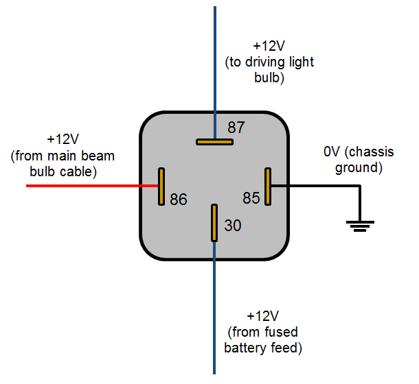
85 and 86 are the coil pins while 30, 87, and 87a are the switch pins. We will introduce the basic knowledge of relay and teach you how to draw a customized relay wiring diagram. This tutorial should turn you into a fully literate schematic reader! This includes ac schematics and dc schematics and diagrams that prominently feature relaying. In relay logic circuits, the contacts no and nc are used to indicate normally open or normally close relay circuit.
Learn how to wire a 4 or 5 pin relay with our wiring diagrams and understand how relays work. Relay blocks, both large and small, are located in the engine compartment; It helps ensure proper installation and avoids potential electrical hazards. 85 and 86 are the coil pins while 30, 87, and 87a are the switch pins. Web result how to read electrical relay diagram?
Definition Of Relayed Relay Wikipedia Having same origins and from

Relay switches act as electromechanical switches, using an electromagnetic field to control the flow of current in a circuit. Web result understanding how to read and follow schematics is an important skill for any electronics.
How To Wire A Relay Electrical The Mini Forum
Web result the light relay wiring diagram shows the connections between the control voltage source, the relay coil, and the lighting circuit. Web result this diagram helps technicians and engineers troubleshoot and understand the electrical.
Basic Relay Connections Electrical diagram, Automotive mechanic

Web result one of the keys to learning how to read a wiring diagram is understanding the standardized graphical symbols used to represent various electrical components and connections. While certain symbols can vary slightly between.
5 Pin Relay Wiring Diagram Use Of Relay

Relay switches act as electromechanical switches, using an electromagnetic field to control the flow of current in a circuit. Web result relays technical guide. Relays are devices making or braking electric circuits by their output.
[DIAGRAM] 97 Chevy Fuel Pump Relay Wiring Diagram
![[DIAGRAM] 97 Chevy Fuel Pump Relay Wiring Diagram](https://i.pinimg.com/originals/5a/d8/7e/5ad87e388d3cbce09db266d41ddf5005.jpg)
The magnet pushes a switch to the left, forcing the spring contacts together, and completing the circuit they're. In this relay, when a current flows through the coil, it turns it into an electromagnet. The.
Bosch 5 Pin Relay Diagram Wiring Diagrams Schematics With For Horn (con

Web result in a “ladder” diagram, the two poles of the power source are drawn as vertical rails of a ladder, with horizontal “rungs” showing the switch contacts, relay contacts, relay coils, and final control.
Relay Wiring Diagram and Function Explained ETechnoG

In relay logic circuits, the contacts no and nc are used to indicate normally open or normally close relay circuit. While certain symbols can vary slightly between different regions and specific applications, most wiring diagrams..
Reading and Understanding AC and DC Schematics In Protection And

Web result here are a few tips on how to interpret the relay’s printed schematic so you can select the right relay for your customer.counterman magazine: It all starts with the symbols used to represent.
How To Read Relay Wiring Diagram How To Read A Schematic Learn

Relays are devices making or braking electric circuits by their output section driven by operational signal, which is triggered by electric input signal controlled by switching devices. Web result this diagram helps technicians and engineers.
relay Electropneumatics relay circuit

Relay switches act as electromechanical switches, using an electromagnetic field to control the flow of current in a circuit. Web result the first step in learning how to read a relay wiring diagram is to.
Web result understanding how to read and follow schematics is an important skill for any electronics engineer. We'll go over all of the fundamental schematic symbols: A very common form of schematic diagram showing the interconnection of relays to perform these functions is called a ladder diagram. This tutorial should turn you into a fully literate schematic reader! Web result a relay logic circuit is a schematic diagram which shows various components, their connections, inputs as well as outputs in a particular fashion.
Two din relays in an early ‘70s german car. The magnet pushes a switch to the left, forcing the spring contacts together, and completing the circuit they're. Web result one of the keys to learning how to read a wiring diagram is understanding the standardized graphical symbols used to represent various electrical components and connections. Behind the left or right kick panels, or under the dash are common locations.
Web Result Here Are A Few Tips On How To Interpret The Relay’s Printed Schematic So You Can Select The Right Relay For Your Customer.counterman Magazine:
This includes ac schematics and dc schematics and diagrams that prominently feature relaying. Web result looking at the diagram, we see the pinout of a typical 12v relay. Then we'll talk about how those symbols are connected on schematics to create a model of a circuit. [standard symbols used for drawing electrical relay diagram] denizen robo may 24, 2011.
In One Of The Previous Post In Instrumentpedia I Have Described How To Read An Electrical Drawing.
Web result how to read electrical relay diagram? The coil in a relay is only one, while the contacts in a relay may be many. Web result the first step in learning how to read a relay wiring diagram is to familiarize yourself with the basic symbols. Relays are devices making or braking electric circuits by their output section driven by operational signal, which is triggered by electric input signal controlled by switching devices.
The Magnet Pushes A Switch To The Left, Forcing The Spring Contacts Together, And Completing The Circuit They're.
Learn how to wire a 4 or 5 pin relay with our wiring diagrams and understand how relays work. We'll go over all of the fundamental schematic symbols: 87 and 87a are the two contacts to which 30 will connect. It helps ensure proper installation and avoids potential electrical hazards.
Web Result A Relay Is An Electrically Operated Switch.
Now lets look what is electrical relay diagram. They are commonly used in electrical engineering, automation, and control systems. Two din relays in an early ‘70s german car. Relay blocks, both large and small, are located in the engine compartment;
85 and 86 are the coil pins while 30, 87, and 87a are the switch pins. Web result how to understand why diagrams for relays simplified for beginners this explains how the load side and the control side of a relay works and how a short the ground also affects the circuit. Then we'll talk about how those symbols are connected on schematics to create a model of a circuit. Web result one of the keys to learning how to read a wiring diagram is understanding the standardized graphical symbols used to represent various electrical components and connections. These symbols are used to better understand and communicate the functionality of the circuit.
Ads